Introduction and Project Overview
The Millau Viaduct (Viaduc de Millau) stands as one of the most remarkable achievements in modern civil engineering, crossing the Tarn Valley near Millau in southern France. This cable-stayed bridge represents a seminal infrastructure project on the A75 motorway, ultimately connecting Clermont-Ferrand to Montpellier and forming part of the crucial Paris-Barcelona route. The structure began construction in October 2001 and was completed in January 2005, with the bridge opening to traffic on December 16, 2004.
Record-Breaking Specifications
The viaduct holds multiple world records and impressive technical specifications:
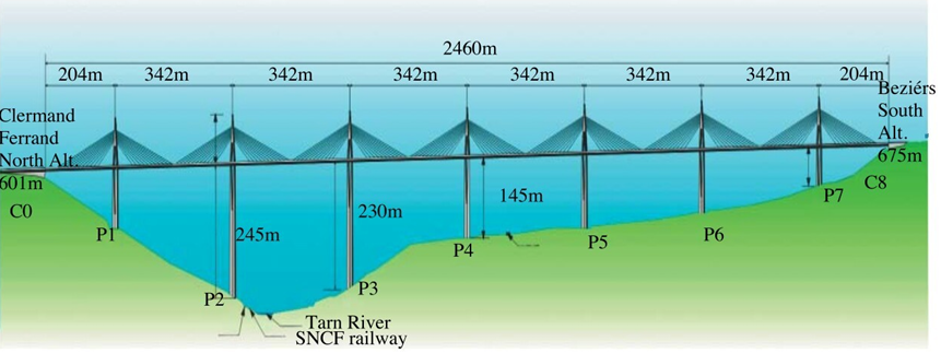
- Total Length: 2,460 meters (approximately 2.5 km)
- Maximum Height: 343 meters at the tallest pylon (19 meters taller than the Eiffel Tower)
- Bridge Type: Multi-span cable-stayed bridge with 7 main piers
- Tallest Pier: P2 at 245 meters (world record for bridge piers)
- Deck Height Above Valley: 270 meters above the Tarn River
- Bridge Width: 32 meters total, with deck width of 27.75 meters
- Gradient: 3.025% slope from North to South
- Curvature: Gentle curve with radius of 20 kilometers
Historical Context and Project Genesis
The Traffic Problem
Before the viaduct’s construction, the absence of a direct route across the Tarn Valley created severe bottlenecks in Millau, particularly during summer months of July and August when tourist traffic peaked. Travelers were forced to descend into the valley and navigate through the town, often spending hours in traffic jams that could extend journey times by up to 4 hours.[1][2]
Design Competition and Selection Process
The project underwent extensive evaluation of multiple solutions:[2]
Initial Alternatives Considered:
- Low Solution: Road descending into the valley
- High Solution: Bridge 200 meters above the valley (ultimately selected)
The high solution was preferred due to:[2]
- Enhanced safety considerations
- Economic benefits (shorter and cheaper route)
- Reduced environmental impact
- Minimal urban disruption
- Preserved access to Millau via interchange
Bridge Design Proposals
Seven different bridge types were initially studied, with four main projects retained for detailed consideration:[2]
- Large span design: 280m span above Tarn with concrete deck
- Steel variant: Same as project 1 but with steel deck
- Cable-stayed spans: 320m spans with concrete deck
- Extended cable-stayed: 400m span with 170m access spans and steel deck
Design Team and Architecture
- Principal Architect: Sir Norman Foster (Foster + Partners, UK)
- Chief Structural Engineer: Michel Virlogeux (France) – original designer of Normandy Bridge
- Main Contractor: Eiffage Group
- Steel Construction: Eiffel Construction Métallique
- Selection Committee Chair: Christian Leyrit (Director of Roads)
The final design was selected on July 12, 1996, based on the quality of technical and architectural design, execution timeline, and cost-effectiveness compared to other solutions.[2]
Detailed Technical Specifications
Structural Configuration[1][2]
| Component | Specification |
| Span Configuration | 6 main spans of 342m + 2 end spans of 204m |
| Number of Piers | 7 concrete piers varying in height |
| Pylon Height | 87 meters above pier tops |
| Cable Configuration | 154 stay cables (11 pairs per pylon) |
| Deck Type | Trapezoidal steel box girder |
| Deck Depth | 4.2 meters |
| Foundation Type | 4 reinforced concrete piles per pier |
Materials Quantification[1][2]
Concrete Works:
- Total concrete volume: 85,000-127,000 m³
- Pier concrete: Post-tensioned reinforced concrete
- Foundation concrete: 6,000 m³ for piles alone
- Reinforcement steel: 10,000 tonnes for piers, 13,450 tonnes for bases, 1,200 tonnes for piles
Steel Construction:
- Total steel weight: 36,000-43,000 tonnes
- Stay cables: 5,000 tonnes of prestressed steel
- Cable configuration: 55-91 high tensile steel strands per stay
- Welding material consumption: 150 tonnes total
Foundation Design and Geotechnical Engineering
Soil Conditions and Challenges[1]
The foundation design had to accommodate varying soil conditions across the valley:
- Limestone bedrock: Generally stronger mechanical properties
- Marls (clay-limestone mixture): Weaker properties with superficial sliding issues
- Valley bottom variations: Different foundation depths required
Foundation System Design[1]
Each of the 7 main piers rests on a sophisticated foundation system:
Standard Foundation Configuration:
- 4 reinforced concrete piles per pier
- Pile diameter: 5 meters standard, expanding to 7 meters in marls
- Pile depth: 10-15 meters drilled into bedrock
- Base plate thickness: 3.5 meters reinforced concrete footing
- Connection: Monolithic bond between footing and pier base
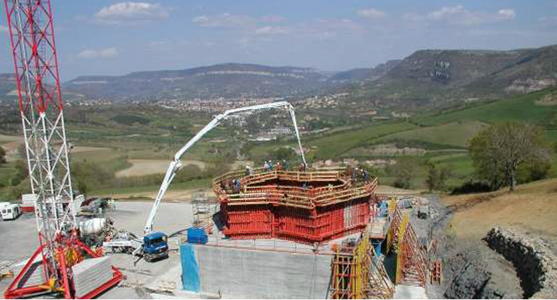
One of the seven foundations for the piers
Foundation Design Philosophy:
- Load transfer: Primarily through end-bearing on rock
- Simplified analysis: Assumed no skin friction except under tension
- Safety factors: Terzaghi’s equations adapted for load inclination and hillside proximity
Geotechnical Analysis Methods[1]
Bearing Capacity Calculations:
- Used Terzaghi’s modified equations accounting for:
- Load inclination effects
- Proximity to hillsides
- Overall stability analysis for marly slopes
- Special stability analysis for Pier 3 requiring soil retaining wall
Testing Program:
- Multiple pile loading tests in marly soils
- Assessment of skin friction along pile shafts
- Ultimate and serviceability limit state combinations
- Evaluation of vertical load distribution and moments
Construction Process and Innovation
Phase 1: Foundation and Pier Construction (2001-2003)
Foundation Installation
- December 14, 2001: First stone laid, marking construction commencement
- Excavation: Precise drilling to 14-meter depths in challenging limestone with cavities and fissures
- Pile Installation: 4 piles per pier, 5-meter diameter, using specialized drilling equipment
- Base Construction: 6-meter deep base for tallest pier P2
Pier Construction Innovation – Automatic Climbing System (ACS)
Elevation Of The Millau Viaduct
Revolutionary Construction Method:
- System Type: Rail-mounted climbing formwork
- Pour Height: 4-meter sections per cycle
- Advantages:
- Consistent concrete quality
- Enhanced worker safety at extreme heights
- Reduced construction time
- Precise dimensional control
ACS Operation Process:
- Initial pier section poured using conventional shuttering
- Rail system attached to completed concrete section
- Climbing mechanism moves formwork up rails independently
- 4-meter concrete lifts poured with precision accuracy
- System climbs to next level automatically
Pier Characteristics:
- Tapering design: Narrowing from top to bottom for aesthetic and structural efficiency
- Identical geometry: All 7 piers have same cross-section, varying only in height
- Tallest pier (P2): 245 meters – world record for bridge pier height
- Construction rate: Accelerated schedule achieved through ACS efficiency
Phase 2: Deck Construction and Launch (2003-2004)
Steel Deck Design Rationale
Material Selection Logic:
- Steel vs. Concrete Comparison:
- Concrete deck: 200,000 tonnes, 7 meters deep
- Steel deck: 36,000 tonnes, 4 meters deep (82% weight reduction)
- Construction method compatibility with launching technique
- Enhanced ductility for construction loads
Deck Profile Design:
- Cross-section: Trapezoidal box girder optimized for weight and strength
- Sectional fabrication: 18 sections of 171 meters each
- Factory prefabrication: Components manufactured off-site for quality control
Innovative Launch System[2]
On-Site Assembly Factories:
Three specialized 171-meter work zones established behind each abutment:
- Zone 1: Central box girder assembly
- Zone 2: Additional elements integration and joining
- Zone 3: Final assembly, painting, and wind screen installation
Launch Mechanism – ENERPAC Hydraulic System:
The revolutionary launching system employed sophisticated hydraulic translators:[2]
Translator Components:
- Raising capacity: 250 tonnes per translator
- Advancing capacity: 120 tonnes combined force
- Movement increment: 600mm per cycle
- Launch rate: 10 meters/hour (16 cycles per hour)
- Control system: GPS and laser alignment for millimeter precision
Launch Sequence (5-Step Process):
- Initial Position: Deck weight supported by balance jacks through orange cradle
- Raising: Blue wedge forces plates apart, lifting deck clear of cradle
- Advancing: Deck moves forward 600mm while suspended
- Lowering: Deck settles back onto support cradle
- Return: Advance plate returns to starting position for next cycle
Launch Nose System:
- Purpose: Facilitate docking onto supports and provide emergency stability
- Control: Two hydraulic cylinders for rotation control
- Adjustment mechanism: Special bar jacks with 270-tonne cylinders and 205mm travel
- Safety feature: Emergency stop capability in high winds
Deck Assembly Specifications[2]
Welding Requirements:
- Workforce: 75 welders per assembly area
- Welding material: 5 tonnes per 171m section
- Total consumption: 150 tonnes welding material for entire structure
- Assembly time: 4 weeks per section after initial bedding-in period
Quality Control:
- Material specifications: DI-MC 460 TMCP steel (thin, high-strength, weldable)
- Steel grades: S355/S460 qualities for different components
- Surface treatment: Complete painting and protective coatings
- Precision requirements: Millimeter accuracy in positioning
Phase 3: Final Assembly (2004)[1][2]
Historic Deck Closure
- May 28, 2004: North and south deck sections joined above Tarn River
- Meeting height: 268 meters above valley floor
- Precision achievement: Closure accomplished within centimeters tolerance
- Structural completion: Continuous deck span achieved
Pylon Installation and Cable Tensioning
Pylon Transportation and Erection:
- Fabrication: Off-site manufacturing with on-site assembly
- Weight per pylon: 700 metric tonnes
- Transportation: Specialized crawler transporters
- Convoy weight: 8 MN (massive load test for structure)
- Erection method: Horizontal positioning followed by tilting using temporary cable-stayed support tower
Stay Cable Installation:
- Total cables: 154 stay cables
- Cable composition: 55-91 high tensile steel strands per cable
- Protection system: Three-layer galvanization, petroleum wax coating, polyethylene sheath
- Anti-vibration design: Double helix formation to prevent water running and vibration-induced damage
- Installation contractor: Freyssinet (specialized cable tensioning)
- Tension range: 900-1200 tonnes for longest cables
Structural Engineering Analysis
Loading Considerations[1]
The bridge design required comprehensive analysis of multiple loading scenarios:
Dead Loads[1]
- Primary: Steel deck structure
- Secondary: Wind screens, cornices (affecting aerodynamics)
- Cable systems: Stay cables and fixings
- Pylons: Steel pylon structures
Superimposed Dead Loads[1]
- Road surface: Specialized blacktop developed for the bridge
- Safety systems: Concrete and steel crash barriers, handrails
- Drainage systems: Complete water management infrastructure
- Utilities: Lighting and monitoring systems
Live Traffic Loads[1]
- Standard loading: HA and HB loading configurations per British/French standards
- Load positioning: Most adverse locations for maximum effect
- Traffic types: Standard vehicles and heavy goods vehicles
- Load distribution: 9.5 kN/m for spans (adjusted for actual design)
Wind Loading Analysis[1]
Critical Design Consideration:
- Valley effects: Funneling and acceleration of wind speeds
- Height exposure: Extreme wind loads at 270+ meter elevation
- Aerodynamic design: Comprehensive wind tunnel testing program
- Deck optimization: Streamlined profile to minimize wind resistance
Wind Engineering Process:
- Directional wind pattern identification
- Statistical analysis of local meteorological data
- Wind action mechanisms analysis (steady, gust, wake forces)
- Structural response modeling
- Wind tunnel parameter derivation
- Quality control of experimental results
Temperature Effects[1]
Thermal Design Parameters:
- Design temperature range: -35°C to +45°C
- Bridge length: 2,460m requiring extensive thermal movement accommodation
- Expansion analysis: Stress calculations with expansion joints blocked
- Differential heating: Upper/lower deck surface temperature variations
- Time-dependent effects: Daily and seasonal thermal cycling
Construction Loading[1]
Unique Construction Challenges:
- Cantilever spans: 171m unsupported spans during launch
- Temporary loading: Higher stresses during construction than service
- Deflection control: Visible undulation during launch phase
- Steel ductility: Advantage of steel in handling construction stresses
Structural Behavior Analysis[1]
Cable-Stayed System Mechanics[1]
Multi-Span Configuration:
- No back-stays: Unlike typical cable-stayed bridges
- Load interaction: Adjacent spans directly influence each other through pylon flexibility
- Pylon design: Relatively low bending stiffness compared to piers
- Load path: Cable forces resolved through A-frame pylon geometry
Foundation-Structure Interaction[1]
Complex Behavior Modeling:
- Piled raft system: Combined foundation and footing load sharing
- Simplified analysis: Conservative assumption of pile-only bearing
- Rock bearing: Ultimate pressure calculations at pile base
- Settlement analysis: Rock deformation at pile base level
Wind Engineering and Aerodynamics
Deck Design Optimization[2]
Two alternative deck designs were wind tunnel tested to ensure aerodynamic stability:
Design Requirements:
- Flutter prevention: Critical at extreme bridge height
- Vortex shedding control: Minimizing dynamic amplification
- Cross-wind stability: Vehicle safety in high winds
- Maintenance access: Wind shields for pedestrian safety
Final Deck Configuration:
- Streamlined profile: Optimized trapezoidal section
- Wind ducts: Integrated air flow management
- Protective screens: Transparent panels to maintain visibility
- Emergency protocols: Real-time wind monitoring system
Environmental Integration[2]
Landscape Considerations:
- Visual impact: Slender profile minimizing visual intrusion
- Curve design: 20km radius curve for landscape harmony
- Height strategy: Minimal valley floor impact
- Architectural philosophy: Integration with natural topography
Economic Analysis and Financial Engineering
Project Financing Structure[2]
Build-Finance-Operate-Transfer (BFOT) Model:
- Concessionaire: Eiffage Group through subsidiary company
- Concession period: 75 years operational + 3 years construction
- Revenue source: User tolls exclusively
- Risk allocation: All construction and operational risks with private partner
Capital Expenditure:
- Project development: €15 million
- Preliminary works: €10 million
- Construction and delivery: €320 million
- Regional development contribution: 1% of construction cost
- Total project cost: €345 million
Toll Revenue Structure:
- Summer rates (July-August): €6.50
- Standard rates (remaining year): €4.90
- Traffic differentiation: Seasonal pricing strategy
- No government subsidies: Entirely self-funded through tolls
Traffic Performance and Revenue[2]
Traffic Volumes:
- 2005: 4,400,000 vehicles (20% above forecast)
- 2008: 4,670,449 vehicles
- Heavy goods traffic: 8.39% of total traffic
- Daily variation: 2,500 to 62,300 vehicles (summer peaks)
- Annual tourism visits: 600,000-900,000 visitors
Operational Infrastructure:
- Toll lanes: 14 lanes initially, expanded to 18 lanes by 2005
- Workforce: 54 permanent cashiers + 33 summer additions
- Manual collection: Due to A75 being otherwise toll-free
- Additional services: Security, maintenance, communication/tourism
Innovation and Technical Achievements
Construction Innovations[2][1]
Automatic Rail Climbing System (ACS)
Revolutionary Formwork Technology:
- Precision: Millimeter accuracy in concrete placement
- Safety: Reduced worker exposure at extreme heights
- Efficiency: Consistent 4-meter pour cycles
- Quality: Uniform concrete strength and finish
- Speed: Accelerated construction timeline
Hydraulic Launch System
ENERPAC Innovation:
- Precision control: GPS-guided positioning system
- Heavy lifting: 250-tonne capacity per translator
- Continuous operation: 16 cycles per hour capability
- Safety systems: Emergency stop and load monitoring
- Adaptability: Variable terrain and grade accommodation
Material and Design Innovations[2]
Advanced Steel Technology
High-Performance Materials:
- DI-MC 460 TMCP steel: Thin, high-strength, weldable
- Corrosion protection: Multi-layer protective systems
- Prefabrication quality: Factory-controlled manufacturing
- Weight optimization: 82% reduction versus concrete alternative
Cable Technology
Stay Cable Specifications:
- Protection system: Triple-layer corrosion protection
- Anti-vibration design: Double helix strand configuration
- Tensioning precision: Computer-controlled installation
- Load capacity: Up to 1,200 tonnes per cable
- Durability: 120-year design life
Environmental and Social Impact
Traffic Flow Transformation[2][1]
Congestion Relief:
- Time savings: 4-hour delays reduced to minutes
- Route efficiency: Direct A75 connection maintained
- Economic benefits: Enhanced regional connectivity
- Tourism boost: Bridge itself became major attraction
Regional Economic Impact[2]
Direct Benefits:
- Construction employment: Thousands of jobs during 3-year build
- Operational employment: Permanent workforce of ~100 people
- Tourism revenue: Major regional attraction generating substantial visitor spending
- Transportation efficiency: Reduced logistics costs for commercial traffic
Indirect Benefits:
- Regional accessibility: Enhanced connectivity to Mediterranean markets
- Urban development: Reduced through-traffic in Millau center
- Environmental: Reduced emissions from traffic delays
- Cultural: International recognition for engineering excellence
Awards and International Recognition[1]
Major Awards:
- 2006 IABSE Outstanding Structure Award: International recognition for structural excellence
- “Mother of All Bridges”: Global engineering community acclaim
- Multiple design awards: Architecture and sustainability recognition
- Engineering landmark: Featured in international engineering curricula
Technical Specifications Summary
| Parameter | Specification |
| Bridge Type | Multi-span cable-stayed |
| Total Length | 2,460 meters |
| Maximum Height | 343 meters (pylon top) |
| Deck Width | 27.75 meters (32m total) |
| Number of Spans | 8 (6×342m + 2×204m) |
| Number of Piers | 7 concrete piers |
| Tallest Pier | P2: 245 meters |
| Pylon Height | 87 meters above piers |
| Stay Cables | 154 total (11 pairs per pylon) |
| Deck Type | Steel trapezoidal box girder |
| Deck Depth | 4.2 meters |
| Gradient | 3.025% North to South |
| Curve Radius | 20,000 meters |
| Foundation | 4×5m diameter piles per pier |
| Pile Depth | 10-15 meters into bedrock |
| Design Life | 120 years minimum |
| Wind Resistance | 250 km/h sustained winds |
| Construction Period | 38 months (Oct 2001-Dec 2004) |
| Opening Date | December 16, 2004 |
| Material | Quantity |
| Concrete | 85,000-127,000 m³ |
| Structural Steel | 36,000-43,000 tonnes |
| Stay Cables | 5,000 tonnes prestressed steel |
| Reinforcement | ~25,000 tonnes total |
| Welding Material | 150 tonnes |
| Foundation Concrete | 6,000 m³ (piles only) |
Conclusion and Legacy
The Millau Viaduct represents the pinnacle of early 21st-century bridge engineering, combining record-breaking scale with innovative construction methods and elegant architectural design. The successful collaboration between French engineering expertise (Michel Virlogeux) and British architectural vision (Sir Norman Foster) created a structure that not only solved critical transportation challenges but also became a global icon of engineering achievement.[2][1]
Key Success Factors[2]
Technical Excellence:
- Innovative construction methods: ACS and hydraulic launch systems
- Material optimization: Strategic use of high-performance steel
- Precision engineering: Millimeter-accurate assembly at extreme scale
- Risk management: Comprehensive analysis and mitigation strategies
Project Management:
- Integrated design approach: Architecture and engineering collaboration
- Advanced planning: Thorough pre-construction analysis and testing
- Quality control: Factory prefabrication and systematic assembly
- Schedule performance: Completed ahead of schedule and within budget
Financial Innovation:
- BFOT procurement: Successful public-private partnership model
- Risk allocation: Appropriate distribution between public and private sectors
- Revenue optimization: Effective toll pricing strategy
- Long-term sustainability: Self-financing operational model
The Millau Viaduct continues to serve as a benchmark for major infrastructure projects worldwide, demonstrating how technical innovation, architectural vision, and sound project management can deliver transformative infrastructure that serves both functional and inspirational purposes. Its success has influenced bridge design and construction methodology globally, establishing new standards for tall bridge construction and cable-stayed design.[1][2]
Future Relevance:
As climate change and urbanization create new infrastructure challenges, the Millau Viaduct’s lessons in sustainable design, environmental integration, and innovative construction methods remain highly relevant for future mega-projects worldwide. The bridge stands not just as a transportation link, but as a testament to human engineering capability and the power of international collaboration in creating lasting infrastructure for future generations.[1][2]
⁂